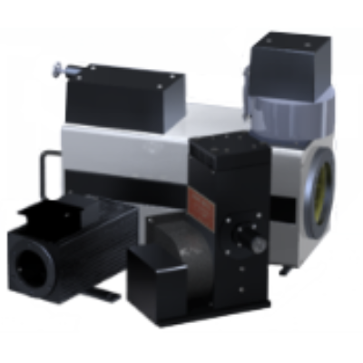
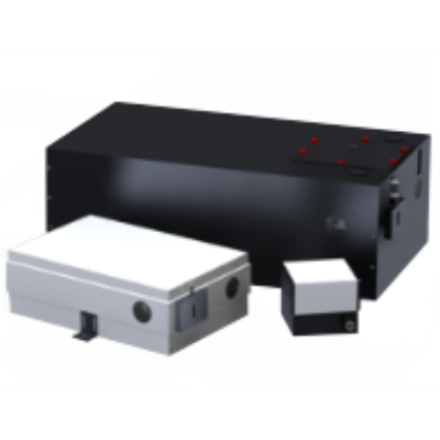
Standard Series
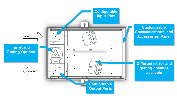
| Step 1: Choose Chassis and F / # | ||||
| Part # | Model | F / # | Focal Length | Turret Configuration |
| 120-9018 | 9055 | F / 3.5 | 200 / 250 | Triple Grating |
| 120-9023 | 9055F | F / 2.5 | 200 / 250 | Double Grating |
| 120-9008 | 9057 | F / 5.9 | 500 | Triple Grating |
| 120-9042 | 9057F | F / 5.9 | 500 | Double Grating |
| 120-9017 | 9055DX | F / 3.5 | 200 / 250 | Triple Grating |
| Step 2: Choose Input Port Configuration | |
| Part # | Description |
| 120-8042 | Side Input Port |
| 120-8030 | Dual Input Port |
| 120-8072 | Motorized Input Port |
| Step 3: Choose Output Port Configuration | |
| Part # | Description |
| 120-8043 | Side Output Port |
| 120-8031 | Dual Output Port |
| 120-8073 | Motorized Output Port |
There are three basic parameters to consider when choosing a grating for your standard series monochromator
The wavelength range available to you is determined by the grating groove density chosen and the angular mechanical limitation of the monochromator.
Ruled gratings may be blazed to increase their efficiency over a specific wavelength band. Holographic gratings can be modulated such that they are more efficient at some wavelengths then at others. Grating efficiency curves are the best tool for determining the most efficient grating available for your application. It is important to note that grating efficiency curves do not represent the exact efficiency that should be expected when the grating is used in a monochromator as grating efficiency curves are taken at Littrow angle.
Resolution is a measure of an instrument’s ability to separate adjacent spectral lines. Resolution is generally given in nm. The bandwidth (or bandpass) is the wavelength range that falls on the output port at any one time and is also given in nm. This is an important parameter when integrating a camera such as a linear array or CCD on the output port of the monochromator.
| Grating Selection Table for 200 / 250mm Focal Length Monochromators | |||||||
| Grating (I / mm) | 75 | 150 | 300 | 600 | 1200 | 1800 | 2400 |
| Dispersion (nm / mm) | 66.6 | 33.3 | 16.7 | 8.3 | 4 | 2.8 | 2.1 |
| Resolution (nm) | 3.75 | 1.6 | 0.8 | 0.4 | 0.2 | 0.134 | 0.1 |
| Bandwidth (nm) | 1200 | 600 | 300 | 150 | 75 | 32.5 | 16.25 |
| Maximum Suggested Wavelength (nm) | 13900 | 6950 | 3475 | 1737 | 868 | 579 | 434 |
| Maximum Realistic Wavelength (nm) | 21891 | 10945 | 5472 | 2736 | 1386 | 912 | 684 |
| Maximum Wavelength Attainable (nm) | 25377 | 12688 | 6344 | 3172 | 1586 | 1057 | 793 |
Standard mirror coatings are aluminium with a MgF2 protective layer. Standard gratings have an aluminium coating. metallic coating. If your application would benefit from different mirror or grating coatings please refer to the codes below at the time of order.
| Mirror or Grating Coating | Useful Range | Code |
| Aluminium (MgF2 coating) | 350nm + | Standard |
| UV enhanced Aluminium | 200nm + | - UV |
| Silver | 400nm + | - S |
| Gold | 600nm - Far IR, best option for NIR | - G |
Standard Czerny-Turner type monochromators suffer from astigmatism in the output beam due to the use of off-axis spherical mirrors. Often the astigmatism is not an issue. For imaging applications a toroidal mirror is used to compensate for the inherent astigmatism in the optical system produce a direct image of the input slit at the output port. This is an important option for studying phenomena such as fast kinetics.
| Imaging Option | Note | Code |
| 9055-i Monochromator (previously 9060) | For 120-9018 Chassis only | 120-9060 |
| 9057-i Monochromator | For 120-9008 Chassis only | 120-9061 |

