Quantum Efficiency
A complete guide to the essentials of quantum efficiency
What is Quantum Efficiency?
Quantum efficiency (QE) is a measure of the number of charge carriers created per the number of incident photons of a given wavelength. As this measurement is wavelength-dependent, it yields a graph of QE by wavelength, such as Figure 1.
QE is also known, perhaps more descriptively, as Incident Photon to Converted Electron (IPCE) ratio.
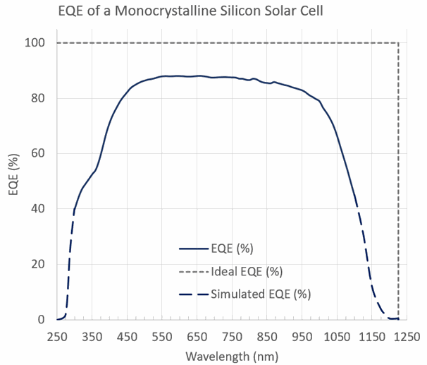
Figure 1.QE measurement of a monocrystalline silicon reference cell. Data gathered using PTS-2-QE quantum efficiency measurement system, from 400-1100 nm. Data from 200-400 and 1100-1200nm simulated and added for illustrative purposes.
In a photovoltaic device, if 100 photons incident on the surface of the cell yield 100 signal electrons, this would be a QE of 100%. In reality, of course, QE values will vary, between and within different PV technologies. Note that if the incident photon has sufficient energy, it may produce more than one electron-hole pair, yielding a quantum efficiency of >100%.
Quantum Efficiency versus Spectral Response
Quantum efficiency (QE) and spectral response (SR) measurements are the same measurement expressed in different units.
Quantum efficiency represents the ratio of electrons output by the photovoltaic device relative to the number of photons incident upon it. Spectral response gives the ratio of current generated by the photovoltaic device to power incident upon it.
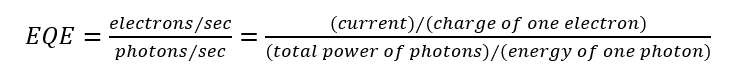
External quantum efficiency (EQE,equation 1) is the measure of the number of signal electrons created per incident photon of a given wavelength. It is a measure of the cell’s external properties, and includes (does not separate out) the effects of losses such as reflectance.
Quantum efficiency represents the ratio of electrons output by the photovoltaic device relative to the number of photons incident upon it. Spectral response gives the ratio of current generated by the photovoltaic device to power incident upon it.
Identifying and accounting for these losses from known sources can be very useful for analyzing a cell’s performance.
Since the number of photons and irradiance are related, SR can be defined in terms of QE, as in equation 2:
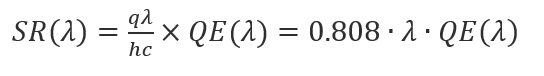
Where:
λ wavelength in μm
h Planck’s constant, in J·sec
c speed of light, in m/s
q elementary charge, in C
SR(λ) spectral response at wavelength λ, in A/W
QE(λ) quantum efficiency at wavelength λ
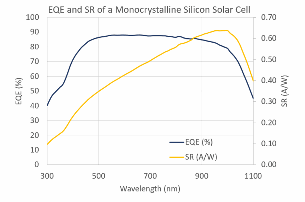
For both QE and SR, the output of the cell decreases at long wavelengths, as the cell cannot absorb photons with energies less than the band gap.
At higher photon energies, each photon has high energy, and energy in excess of the bandgap energy is effectively wasted (contributing only to heating of the cell). This creates a wedge-shaped curve for SR, as the ratio of incident power to output current is lower at shorter wavelengths, due to this wasted energy shown in Figure 2).
QE, on the
other hand, maintains a mostly flat-topped curve, as it considers only the
number of incident photons, rather than their power.
Internal Quantum Efficiency and External Quantum Efficiency
Optical Losses
No solar cell converts 100% of incident photons into electrical energy. When a photon could have generated an electron-hole pair but does not, these are known as optical losses, and are due to reflection of the light or failure of absorption. Some measures can be taken in cell design to mediate these losses.
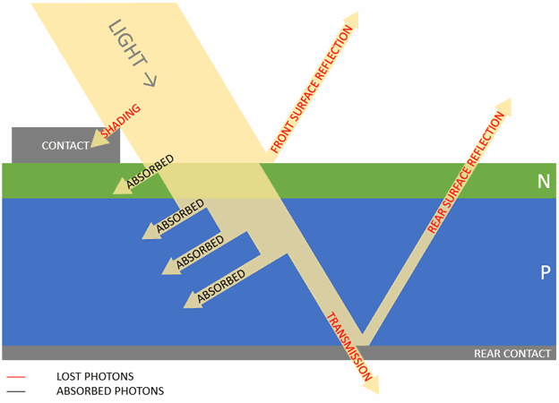
Reflection (Figure 3) can be caused by:
· Front surface reflection
· Rear surface reflection
· Shading from the top contacts covering the cell
Failure of absorption can be caused by:
· Transmission through the cell
· Poor light trapping
· Not being absorbed within the diffusion length (leading to recombination)
Internal Quantum Efficiency
Internal quantum efficiency (IQE) is the measure of the number of signal electrons created per incident photon of a given wavelength that are absorbed by the cell. This removes the effects of transmission and reflection, and is consequently a measure of the internal properties of the cell. The IQE is always larger than the EQE (figure 4).
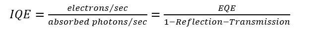
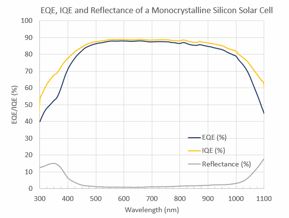
Figure 4. EQE, IQE, and Reflectance curves for a solar cell. IQE (gold) is calculated by removing the effects of reflectance (grey) on the EQE (navy). IQE can also be calculated by removing the effects of both reflectance and transmission.
If the
internal quantum efficiency is known, the total photogenerated current is given
by equation 4:
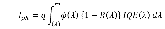
Where:
I ph total photogenerated current
IQE(λ) IQE at wavelength λ, as percentage
ϕ(λ) photon flux incident on the cell at wavelength λ
R(λ) reflection coefficient from the top surface
λ wavelength in μm
Measurement and Calculating External Quantum Efficiency
Measurement of EQE and SR are performed according to the ASTM E1021-15 or IEC 60904-8-2014 standards, the most recent standard test methods for measuring SR in photovoltaic devices.
Equipment
The nominal instrumentation needed to measure EQE consists of:
1. A monochromatic light source for determining EQE by wavelength. This may be a monochromator-coupled light source with diffraction grating and order-sorting filters, a set of optical filters coupled to a broadband source, or a set of narrow wavelength band LEDs.
2. A bias light – a broad-spectrum, one-sun intensity light source that ensures test conditions are similar to operating conditions. This may be a solar simulator.
3. A mechanical chopper and measurement circuitry to distinguish the current resulting from the monochromatic light from the current generated by the bias light or environmental noise. This may be a lock-in amplifier or a true RMS meter.
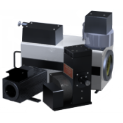
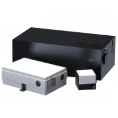
Figure 5 shows a diagram of the main components of an example EQE system (Sciencetech model PTS-2).
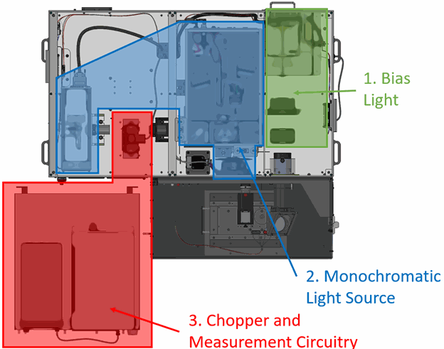
Figure 5.
Diagram of a QE measurement system's nominal components (Sciencetech model PTS-2). The bias light (1) is a xenon short arc lamp combined with spectral filter (producing a class AAA solar simulator). The monochromatic light source (2) is comprised of a broad-spectrum lamp (xenon short arc), coupled to a grating monochromator for wavelength selection, and order sorting filters to reject unwanted wavelengths. The mechanical chopper and measurement circuitry (3) use a lock-in amplifier to isolate the signal from the monochromatic light. Note that the location of the measurement circuity as shown is not the true location of the equipment, they are stored underneath the main body of the PTS-2 system.
To measure
IQE, additional measurements need to be taken to quantify light that is not
absorbed. Depending on the cell technology and construction, just measuring
reflectance may be sufficient, or transmission may be measured as well.
To measure reflectance, there must be a way to collect and measure light reflecting off the cell surface, while transmission is measured by similar collection at the back of the cell.
Commonly, an integrating sphere is placed at an angle to the cell, such that specular and diffuse reflections off its surfaces are captured and measured. Another sphere or optical fiber may be used at a second position behind the cell, to collect and measure transmission.